
Learning Kit for Tendon-driven Continuum Robots
Hi! I am Ankit and I’ve spent my summer 2023 at the CRL developing a learning kit for Tendon Driven Continuum Robots together with Reinhard Grassmann. The learning kit uses CRL’s latest design papers1 2 and builds on the open actuation module. The motivation for the learning kit stems from the Open Continuum Robotics Project’s fundamental objective of empowering the world with open hardware and open software to create their continuum robots.
The idea is something I can relate to largely. Robotics Education is only just taking off in most parts of the world. With this project, I designed something that students at my home university, Manipal Institute of Technology in India, would be able to build. For the design, we considered various constraints such as component availability, 3D printer access, and skill level.
Components
The kit comprises a Tendon Driven Continuum Robot (TDCR), four actuators, two TI Launchpads, various complementary electronic components, and a custom casing to enclose the entire system. For the sake of brevity, I have omitted details thoroughly explained on our GitHub.
Manipulator
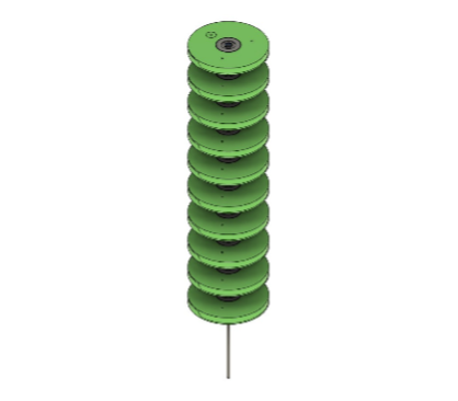
The manipulator of the TDCR consists of 10 Type-II spacer disks equally distributed along a Nitinol Backbone with a diameter of 1.4 mm. The robot is capable of 3 DOFs, namely bending across two planes and rotation about its axis. I used three independently actuated tendons made of Spectra Fiber and an actuator to rotate the backbone, enabling these degrees of freedom.
The body of the spacer disk is fixed to the backbone axially, while a bearing in the middle enables the rotational DOF. It is split into two parts to allow for the insertion of the bearing in the middle. I changed the regular ball bearing to a pulley to reduce the number of unique components. The profile of the two parts allows for easy assembly while ensuring that the actuation through the tendons is optimal. The grooves ensure the adhesive stays inside the segment and does not spill out. A small part, functioning as a spacer to make the pulley bore smaller, is designed with a unique profile that balances the required friction to grip the backbone and the need for a constant curvature.
 |
 |
 |
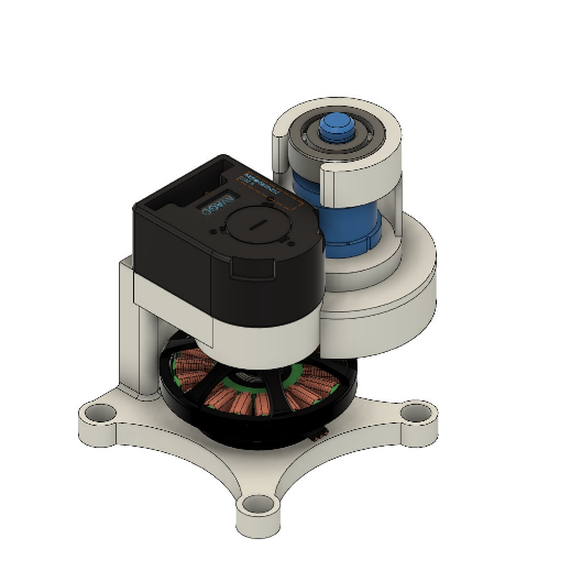
Actuators
Our actuation module was modified to suit this kit’s requirements. I replaced the multi-part casing with a single unit, such that the new case is easier to manufacture while maintaining adequate performance. The assembly process is simplified as the singular casing eliminates input and output shaft misalignment. The motor and the gears can easily fit into designated spaces using dedicated slots. Since the actuator will only actuate tendons, I introduced an extra bearing at the output shaft to handle the increased radial tension and eliminate shaft eccentricity.
I used the Launchpad TI LAUNCHXL-F28069M, a microcontroller development board, to control the motors with two motor Drivers, BOOSTXL-DRV8305EVM. Since four motors and each motor driver can control one motor, two Launchpads and four motor drivers are required to actuate the continuum robot.
 |
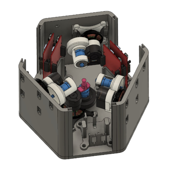 |
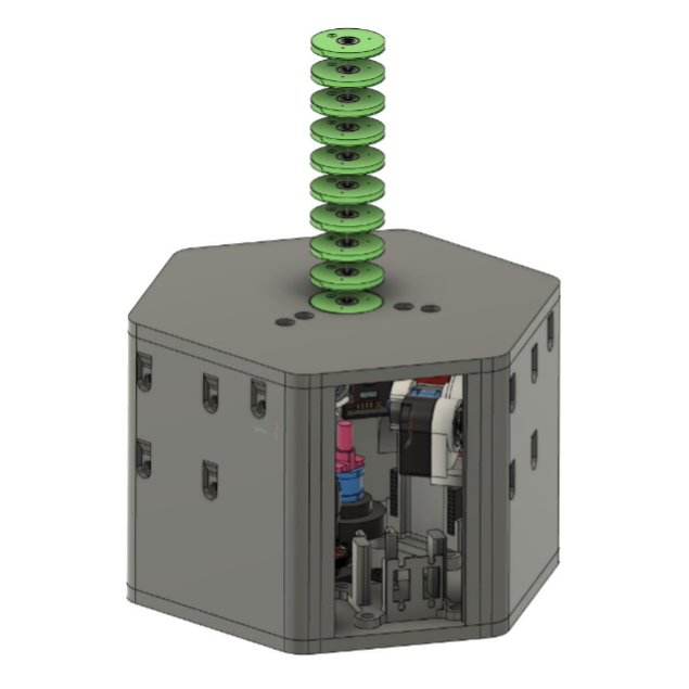
Housing
All components are placed inside a hexagonal casing with windows made of transparent acrylic sheets to view the system’s working. The three tendon actuators are fixed horizontally to reduce tendon routing. Six pulleys are placed inside to help reduce the tendon offset and increase the efficiency of tendon control. One actuation module is placed at the bottom and controls backbone rotation. To secure the electric components in the case, I designed custom 3D-printed mounts. All components are visible from the windows to allow the user to see the robot’s functioning, allowing better understanding and enabling intuition development.
I used several techniques to adapt the design for manufacturing with an FDM 3D Printer:
- teardrop method to ensure optimal vertical holes
- eliminated 90° overhangs using arcs
- used chamfers to reduce support material.
- counterbores for all bolt heads ensure a flush surface finish on all casing sides
- included partial slots for nuts to make assembly easier
Assembly Guide
Find a detailed assembly guide, printable STL Files and mechanical drawings on GitHub and watch the assembly video on YouTube: GitHub Video
I encourage you to try and fabricate this learning kit and contact us regarding any queries or further developments you make! We would love to hear about your experience and see your prototypes!
Epilogue
I took the design home and encouraged robotics enthusiasts at my home university to build and use OpenCR’s Learning Kit. The learning kit allows students to easily understand concepts, design, and implement various algorithms. I hope this kit or its successor will find its way into classrooms at different schools! Stay tuned for updates.
References
-
Reinhard M. Grassmann, Priyanka Rao, Quentin Peyron, Jessica Burgner-Kahrs: FAS — A Fully Actuated Segment for Tendon-Driven Continuum Robots. Front. Robot. AI 9:873446, 2022. doi: 10.3389/frobt.2022.873446 ↩
-
Reinhard M. Grassmann, Chengnan Shentu, Taqi Hamoda, Puspita Triana Dewi, Jessica Burgner-Kahrs. “Open Continuum Robotics – One Actuation Module to Create them All,” 2023, arXiv: 2304.11850 ↩